The MATO U20 Belt Lacing System has specially designed for connecting belts operating in Round Balers. The U20 Systems includes the MATO belt cutter, MATO skiver and MATO belt lacing tool. The system has been proven in controlled tests and extensive field trials. Excellent service life will be achieved if the operating instructions are followed correctly.
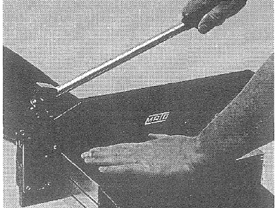
1. Cut belt end square. Optimal result with MATO Belt Cutter.
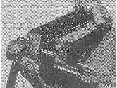
2. Position and clamp the Profi 19 Lacer in a bench vice with the holes facing forward. Lacer must be completely opened.
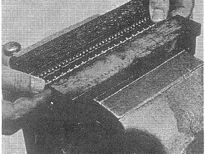
3. Insert rivets of fastener strip in the holes, starting on the left.
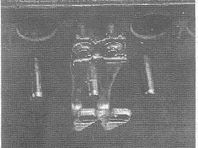
4. Two rivets at a time have to be inserted in one hole.
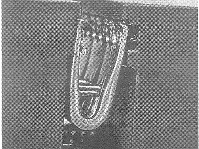
5. Before inserting the belt, tighten vice until fasteners are lightly gripped and the belt can easily be inserted.
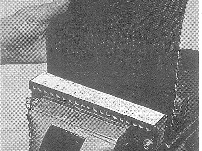
6. Insert first belt end. Set belt edge to marking (belt width or number of fasteners).
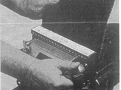
7. Push the belt uniformly down to the stop pins and tighten vice until fasteners are lightly gripped.
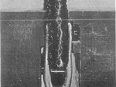
8. The belt has to rest on the stop pins. Close lacer until it touches the belt surface.
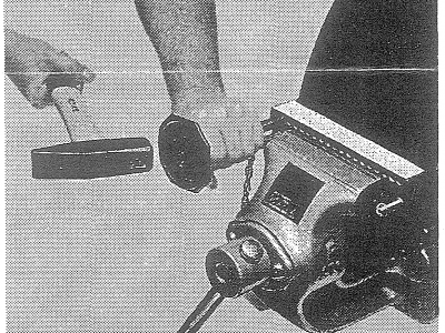
9. Using a I l/2 lb hammer install the first and last fasteners by punching through rivert until punch ford to shoulder.
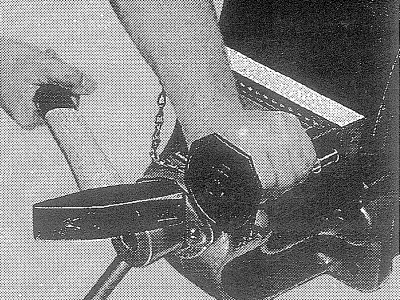
1O. Punch all remaining riverts through, in any sequence until complete.
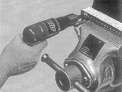
11 . For easier installation a pneumatic hammer with special punch can be supplied. Install in same sequence as with hammer.
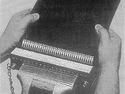
12. Open vice and remove belt by pushing it lightly backwards.
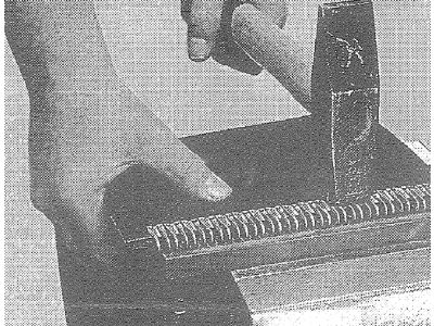
13. Flatten rivets on a solid base.
Take care not to hit or to damage loop area of fastener!
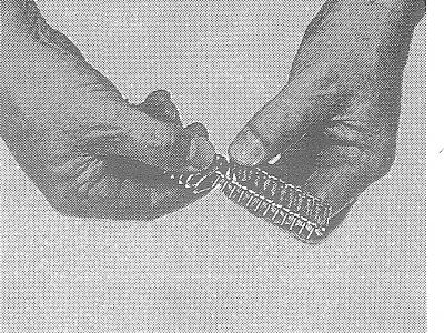
14. For different belt widths, twist off excess hooks.
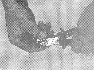
15. Snip off the projecting welding wire!
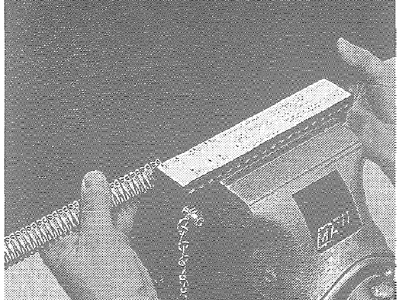
16. Th same lacing method is applicable for all belt widths.
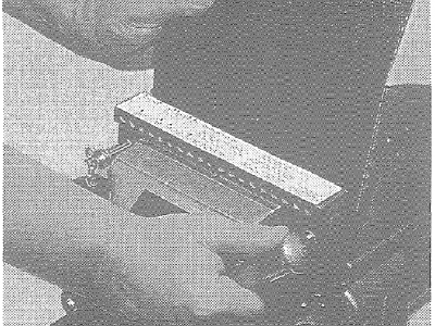
17. Repeat the whole procedure for the other belt end. Attention: the same side of the belt has to face forwards!
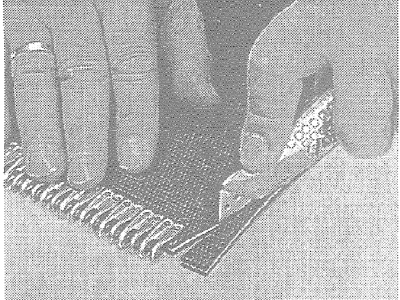
18. Chamfer corners on one belt end only, leaving 1/64″ of belt adjacent to fastener and cutting back 1 1/16″.
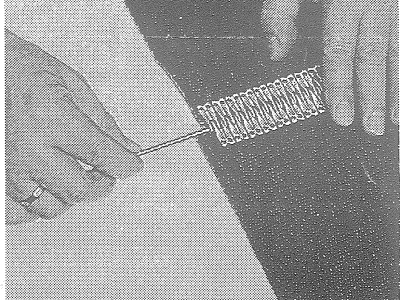
19. To join belt ends interconnect fasteners ensuring belt edges are in line and insert connection pin.
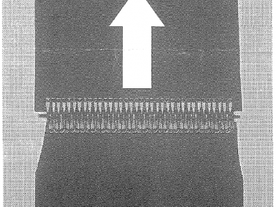
20. The chamfered belt end should run in the trailing position.
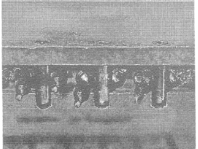
21. For successful splicing remove any trapped rubber particles from the lacing tool using a small wire brush.
